Special Rules for Electric Motor Fire Pump Controllers
June 29, 2022Electric motor fire pump controllers are different from many traditional motor controllers in the world. The major difference is that, with some special exceptions, there are no thermal overloads in the controller or devices designed to protect the motor by shutting off the power circuit. With fire pumps, since they provide such a crucial property and life-saving purpose, they are designed to keep power to the fire pump, even if the motor literally burns up. The fire protection and insurance industries figure that the building property and life being protected is more important than protecting a fire pump motor. In that regard, they are correct and have their priorities straight.
UL/FM fire pump controllers, or “listed” fire pump controllers, are guided by requirements in NFPA 20 and NEC regarding their components, as well as considerations for their installation. Most fire pump
controllers today are “service entrance rated,” which means they can be connected directly to the incoming building service conductors. Just as there is a concern for an inadvertent stopping of a fire pump motor during a fire, there is also a concern that the power supplied upstream to a fire pump can also be inadvertently disconnected. To help minimize that occurrence, the power supply to a fire pump controller must follow specific rules as covered in NFPA 20 and NEC Article 695.
The purpose of this blog is to cover some interesting (and most often encountered) code requirements governing electric motor fire pump controllers. Most of these requirements are thoroughly covered in NFPA 20 (2019), and for the purpose of brevity and overall interest, we are not going to review every item discussed in the code books, but rather take a look at some highlights. Upcoming articles will go into further detail on some of the common required components, plus many additional features of fire pump controllers.
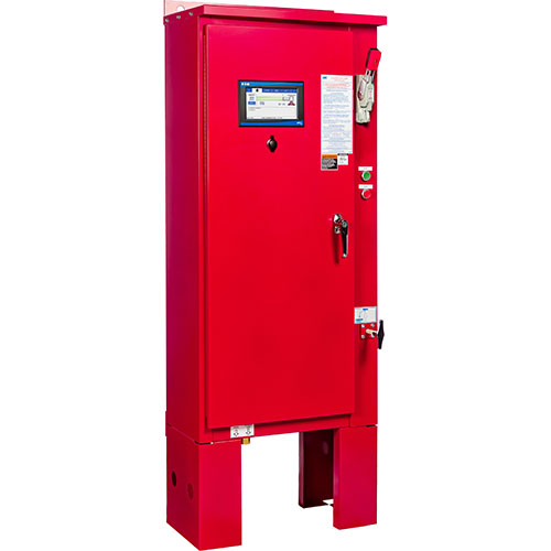
- Location. Fire pump controllers are built to be “service entrance rated,” but not supplied by electrical power that can be inadvertently disconnected. So special care is needed to make sure the upstream electrical complies with NEC Article 695. The physical location of the controller itself must be within sight of the fire pump it is controlling. The controller must be elevated above floor level so that current-carrying components are at least 12 inches off of the floor.
- A controller is not a junction box! Although common in non-fire motor controller practice, you are NOT permitted to use the fire pump circuit breaker to supply power to other equipment. Many times electricians are tempted to do this out of convenience. Do not use a fire pump controller as a junction box!
- Electric fire pump circuit breaker. The circuit breaker in a fire pump controller follows very strict rules regarding mechanical and electrical characteristics. It is factory-set based on motor horsepower and voltage, and is non-adjustable. In other words, don’t tinker with it!
- Integral transfer switch use. Transfer switches with fire pumps are designed to multi-task. They sense and monitor incoming normal power. When a loss of power is detected, the fire pump controller initiates a start circuit to start up the backup generator. Once that backup power is fully available, the power is transferred to the emergency source. So unlike many traditional transfer switches, this moves the transfer of power closer to the fire pump itself, so that if the fire pump controller loses power to a normal source — even if it is from the normal side fire pump circuit breaker itself — emergency power will still be available directly to the fire pump motor. This is quite a reliable electrical power arrangement, with the fire pump getting the highest priority.
- Required local and remote alarms. Since a fire pump controller serves such an important purpose in life safety, any fire pump controller must monitor and initiate specific alarms designed to alert those nearby if there is a problem. These conditions and alarms vary depending on whether your pump is an electric motor-driven one or a diesel-driven pump.
- Enclosure. Mechanical rooms are often humid or damp, so fire pump controller enclosures are required to be, at a minimum, NEMA 2 enclosures. This means they need to be able to protect the internal components literally from moisture drops and from a consistently humid environment. Many common non-fire controllers are designed to NEMA 1 standards.
- Emergency starting. Electric fire pump controllers are required to have a clearly marked external emergency handle to use in case of an emergency where the fire pump needs to be started. This is a simple mechanical method to start the controller. It is designed to be used only in an emergency, such as when the controller fails to start under normal operation or if someone is simply confused and not sure how to operate the controller.
- Tested before shipment. Fire pump controller manufacturers are required to test all functions of their controllers, including local and remote alarm conditions, before the product ships to the jobsite. There is a good level of industry comfort in this. Not only are the controllers in full compliance with NFPA 20, UL, FM, etc., but they are each individually tested to make sure they are operating properly.
Future articles will discuss some of the major components that make fire pump controllers unique. Stay tuned!