Fire Pump Testing – Hose Valve Manifold vs Flow Meter
September 17, 2026Updated September 17, 2026
We will cover fire pump testing, comparing the advantages and disadvantages of two different methods of testing water flow: external water flow through a hose valve manifold on the exterior of a building, versus a flow meter recirculating loop within the mechanical room.
The Traditional Approach: External Hose Valve Manifolds
The traditional method of measuring water flow during a fire pump test has involved the use of a hose valve test manifold, intended to be mounted on the exterior of the building, where 50-foot 2-1/2 inch hoses are then attached to allow for water flow where measurements can be made to the water streams. Hose valve manifolds are fed from a dedicated pipe originating from the fire pump discharge so that flow measurements from the fire pump can be measured while the sprinkler system is isolated.

The specific, recommended procedure of testing a new fire pump installation is outlined in NFPA 20 (2013) Chapter 14. We will not go into the details regarding this testing procedure, but we will point out that the procedure involves discharging water from the fire pump outside of the building, typically through a UL Playpipe nozzle or other device. Once a specific flow is obtained, the fire pump pressure gauge readings are recorded, and the performance of the fire pump can then be compared to its performance curve.
While this method has proven to be very accurate (if done properly), it’s neither environmentally friendly nor efficient. A large volume of water is used for the test while measurements are being taken, and many consider this use of water wasteful. If the water being pumped has been treated with chlorine or other chemicals, the water must be treated to remove chlorine before it is left to dissipate into the ground.
Using a hose valve manifold to test a fire pump requires a team effort — those outside who are measuring the water flow, those who are throttling the hose valves to maintain a directed flow, and those who are in the pump room monitoring the fire pump and are recording the gauge data, shaft rpm, or even electrical volt and amp readings. Any improper coordination between the various participants in the test can result in improper readings.
Pitot Tube Measurement & Logistics
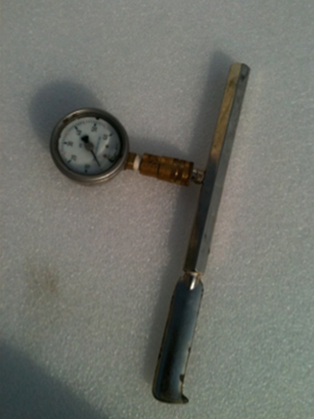
Care must also be taken in exactly how the water measurements are cataloged. The traditional measurement of water during a fire pump test involves the use of a Pitot tube, which must be placed into a stream of water on a precise angle and distance from the water orifice stream. If done manually, this involves an experienced person, and properly secured hoses which are connected to a set nozzle size; using a water flow without a proper nozzle size will not provide an accurate flow measurement.
50 feet of reliable 2-1/2 inch hoses are recommended, and should be kept as straight as possible. A location with good drainage is also preferred for obvious reasons.
Testing a fire pump through use of a hose valve manifold with hoses is also dependent on weather in colder climates. If the weather drops below freezing temperatures, a test using this method is not recommended as it could create an unintended hazard of ice.
Despite the challenges of needing a good place to drain the water, several properly trained individuals to run and monitor the test, proper weather, etc., this method of testing a fire pump has proven to provide the most accurate results.
But the use of a hose valve manifold provides perhaps one of the most valuable tools for an owner of a fire pump — the ability to test not only the fire pump performance but the water supply as well. While releasing water, the suction pressure can be monitored and if there is an obstruction or closed valve supplying the fire pump, this fact will be discovered through the suction gauge readings during the test.
The Modern Alternative: Flow Metering Devices

The use of flow metering devices in fire pump installations has been gaining popularity over the years. Flow meters are devices installed in a water pipe that, if installed properly and in accordance with the manufacturer’s instructions, will provide a visual reading of water flowing at any given moment. By holding a set flow by use of a downstream throttling valve, a large gauge will illustrate the specific flow. Many people prefer to use flow meters in a return loop from the discharge of a fire pump back to the suction of the fire pump. By doing so, they are recirculating all of the water and allow for measurement of water flow all in one place — the mechanical room. While it is possible to use flow meters in any location desired, for the purpose of this article we will address flow meter installations in the common recirculating return loop.
The discharge pressure of a fire pump is lost once the water passes through a circulating flow meter loop. You will end up with equalized suction pressure by the time the water is returned to the fire pump suction. Demonstrating this, however, is outside the scope of this article.
The size of a flow meter is dictated by the fire pump rating in GPM, as referenced in NFPA 20 (2013) Table 4.26 (a) and 4.26 (b). Depending on the manufacturer of the flow meter, a minimum amount of straight pipe is required both before and after the device, so as to minimize water turbulence, and maximize the accuracy of the flow meter. Always follow manufacturer instructions regarding the proper use and location of a flow meter.
Advantages of the Flow Meter Loop
By using a flow meter to test a fire pump you solve many of the problems encountered with the use of a hose valve manifold. With a properly installed flow meter loop, you do not need as many people to perform a test. Often you only need one qualified person to throttle the recirculating water by closing a valve on the downstream side of the flow meter in order to control water flow. Determining water flow is then simply a matter of reading the flow meter gauge. Once that flow is controlled and the water is measured, other pump data is recorded while the pump is running — such as the suction and discharge pressure gauge readings, pump rpm, voltage and amp readings on the controller. While all of this is happening, very little water is lost, since the water passing through the pump is returned to the pump suction.
If your flow meter loop is located indoors, you can also avoid the problem of inclement weather that can postpone or prevent a proper fire pump test, as the entire test can occur within the confines of the mechanical room.
Flow Meter Limitations & Water Supply Verification
But before you decide to replace your external hose manifold with a flow meter, keep in mind that many fire pump flow tests are performed with the intention of verifying not only the fire pump performance, but also the water supply. Testing solely through use of a recirculating flow meter, you are not learning anything about the water supply at all — you are just recirculating water around the pump. While that will measure the pump’s performance, it will tell you virtually nothing regarding the water supply itself. For example, if you have any water obstruction upstream in the suction line, your test data while using a flow meter loop will not detect any problems in the suction line upstream; however, that same obstruction will be evident if flowing water through a test header outside, as the suction pressure will drop off dramatically as water flows during the test. For this reasoning, if your pump is connected to a city main, the initial pump test must be performed through a test header outside and must be duplicated every three years. For the two years in between, the flow meter may be used. An exception to this would be if your flow meter loop terminates to a water storage tank as opposed to the suction line immediately upstream from a fire pump.
Another exception to this would be if the flow meter return line was connected directly to the suction source — like a water storage tank, for example. In this case, use of a flow meter could test both the fire pump performance and water supply simultaneously.
Another challenge in many flow meter installations pertains to “needle jump,” a condition where the visual gauge of the flow meter moves constantly — jumping back and forth due to the turbulence of the water passing through it. If you are after precise water measurements, you are unlikely to obtain them with turbulent water. So it’s wise to size the flow meter return loop with as much straight piping as possible, and perhaps with a line size large enough to slow the water velocity down.
| Feature | Hose Valve Test Manifold | Flow Meter Loop |
|---|---|---|
| Tests Water Supply? | Yes – verifies upstream suction / city main. | No – only recirculates existing water. |
| Water Usage | High – discharges large volumes of water. | Low/None – water is conserved in a loop. |
| Manpower Required | Multiple people (outside, inside, throttling). | Single operator (all from mechanical room). |
| Weather Dependent? | Yes – freezing temps create ice hazards. | No – testing occurs safely indoors. |
| Accuracy | Highest – exact pitot tube measurements. | High – but prone to turbulence (“needle jump”). |
Steven Brown & Associates Recommendation: Choosing the Right Test
We have found that the best installations allow for an external hose valve manifold to allow for a full flow test, which tests both the fire pump and fire pump water supply. A flow meter loop could then be used for interim tests, where discharging water outside is neither feasible nor necessary. A flow meter certainly is more user-friendly and convenient, but not as accurate or as useful as a full water flow test.

Note: This article was written and reviewed by the factory-trained technicians at Steven Brown & Associates. With over 50 years of combined experience, our team performs hundreds of NFPA-compliant fire pump flow tests every year across PA, DE, NJ, and MD.